Installing an in-line UV sterilizer
The unit is spliced into a treated water line — normally the permeate line of an RO system, after the storage tank and before the faucet — using quick-connect fittings on tubing already in place. There is no dedicated circuit and no drain connection: the unit runs on a 100–240 V adapter and starts on water flow. The install itself is small. What decides whether the installation works is not the fitting work but three things that have to be true before the line is cut — that the water reaching the unit is inside the published limits, that the unit is rated at or above the draw of the line, and that there is physically room for it in the position the unit needs.
Not sure the water qualifies?
The limits are conditions of use, not preferences — feed water conditions and warranty.
Planning the retrofit on an RO system?
The same job described from the system side — UV sterilizer for an RO system.

Three checks that cannot be corrected afterwards
An in-line unit has no way of announcing that it is in the wrong place or on water it cannot handle. It installs, it lights, and it looks right. The three checks below are the ones that decide the outcome, and all three have to be made before the tubing is cut — because two of them are about what is upstream, and one of them is about whether the position physically exists.
1 · The water is inside the limits
Turbidity, iron, hardness, pH, chlorine and temperature all affect how much light reaches the organisms. These are published conditions of use and they belong to the upstream treatment, not to the UV unit — the UV stage cannot correct them. Values are on the feed water page and in the datasheets.
2 · The rating matches the draw
Match the unit to the peak draw of the line being protected — not the system's rated output. A unit rated below the draw passes water faster than the design residence time allows, and nothing about the installation will show it.
3 · There is room after the tank
Space for the body, enough tubing length on each side to insert the fittings without straining them, and the warning label still visible once the cabinet is closed. Where the layout does not allow it, that is a layout problem to solve before ordering.
A unit fitted between the membrane and the storage tank, on a line whose draw exceeds its rating, in a cabinet where the run after the tank is too short to reposition it. Every one of those is a decision made before the first cut, and every one of them is invisible at commissioning.
Where the unit goes, and the two places it looks like it should
| Where it is fitted | What the installation achieves |
|---|---|
| On the incoming supply, before treatment | Treats raw water, which is almost certainly outside the unit's published limits, and leaves the tank and the tubing downstream able to re-seed the water. Two problems at once. |
| Between the membrane and the storage tank | Treated water goes straight into the environment that produces regrowth. The barrier sits upstream of the thing it is meant to protect against. |
| After the tank, immediately before the faucet | The specified position. The stage acts after the components that seed the water, on the run that reaches the tap, with nothing downstream of it to undo the work. |
| After a second filter housing or polishing cartridge | Adds another wetted chamber downstream of the barrier. If a polishing stage is wanted, it belongs before the lamp, not after it. |
The installation, in the order it is done
This is a planning outline, not a substitute for the manual. The binding procedure — including the commissioning flush, the leak-check sequence and the feed-water limits — is the one in the manual supplied with the unit you receive.
- Isolate and depressurise the line. Close the supply, shut the unit's power off at the adapter, and open a faucet or the tank valve to release system pressure before cutting. Working on a line that is still pressurised is the most common cause of a joint that weeps.
- Mark the cut-in point on the run after the tank. Allow enough tubing on each side to insert the fittings fully without pulling the run tight, and keep the warning label readable once the cabinet is closed.
- Cut square and dry. A square cut on clean tubing is what makes a quick-connect joint hold. Tubing cut at an angle is the usual reason a joint weeps weeks later rather than immediately.
- Fit and seat the quick-connect fittings. Push the tubing fully home — past the point of first resistance — and fit the locking clips. A tube that is only partly inserted will pass a static leak test and fail under flow.
- Observe the flow direction. The housing carries an inlet marking. Connect so that the supply side of the run reaches the inlet, and check the marking before pushing the tubing home rather than after.
- Secure the unit on the run. Fix it with the U-shaped clamp on the same tubing run, so that the weight of the body is not carried by the joints.
- Commission per the manual. Follow the manual's flush and leak-check sequence, check every joint under pressure — not only the two new ones — and only then close the cabinet.
- Restore power and confirm operation. Draw water and confirm the indicator behaviour, then record the installation date so that the lamp and sleeve intervals start from a known point.
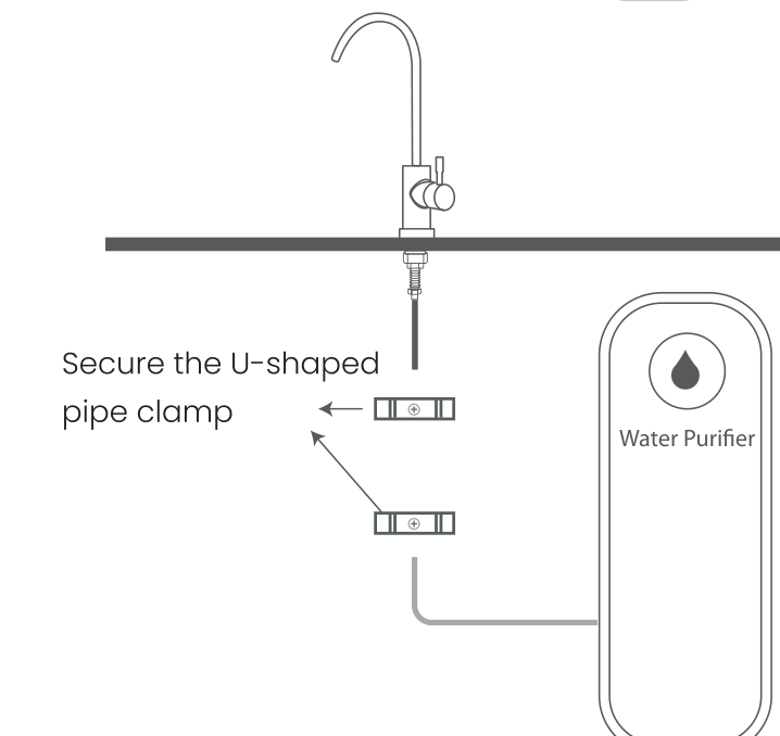
The unit is a component on a flexible-tubing run: no drain connection and no tank modification. Everything above is reversible, and the whole procedure is small — which is exactly why the four steps are worth doing in order rather than roughly.
What a correct installation looks like when it is finished
The adapter is the only electrical part, and it is external to the unit. The installation does not touch the drain, the tank or the supply pressure.
| Check | Why it is on this list |
|---|---|
| Every joint under pressure, including the old ones | Working on a pressurised line disturbs joints that were previously sound. A leak that appears a week later is usually an old joint, not a new one. |
| Flow direction confirmed against the inlet marking | A reversed unit is silent, safe and inert. It is the failure that most often goes out of the door. |
| Indicator confirmed by drawing water | Confirms the flow sensor and the lamp together, in the state the customer will actually use it. |
| Installation date recorded | The service intervals for the lamp and the sleeve start here. Without a date, the first service is guesswork. |
| Feed-water values noted, or a sample taken | The unit's conditions of use are the upstream system's obligations. Writing them down at commissioning is what makes a later water complaint answerable. |
| Manual and warning label left accessible | The label is a safety requirement, not decoration, and the manual is the document that governs future servicing. |
The mistakes that are made, and what each one looks like afterwards
| Mistake | What is observed | What is actually wrong |
|---|---|---|
| Unit fitted before the storage tank | Nothing. Water at the tap is as it was. | The barrier is upstream of the tank, so the water is re-seeded after treatment. The position has to change; the product cannot compensate. |
| Tubing not pushed fully home | Dry at handover, weeping weeks later. | The tube passed the grip ring but not the seal. Under flow, the joint opens slowly. |
| Flow and return reversed | Indicator stays blue with water running. | The flow sensor is on the wrong side of the chamber and never triggers. |
| Unit rated below the draw of the line | Nothing. Indicator behaves normally. | Water is passing faster than the design residence time allows. This is a specification error and cannot be corrected by installation practice. |
| Pre-filter neglected upstream | Complaint about water quality months later. | The UV stage depends on the feed water being within its published limits. Filtration is a condition of use, not an accessory. |
| Body supported by its own joints | Joint begins to seep under movement or vibration. | The weight of the housing is being carried by the fittings instead of the clamp. |
Two values this page deliberately does not give
Both are stated in the manual that accompanies the unit. They differ between documents in circulation, so this page does not restate them: use the figures in the manual supplied with the unit you receive, and ask us if the version you are holding is unclear. A number copied from a web page is not the number to commission to — and where two documents disagree, neither should be published as though it were settled. The same rule applies to the tubing specification for the run: the manual governs.
This is not a gap that a longer page would close. Where the manufacturer's documentation does not yet carry a single figure, the site is written without the figure rather than around it — the conditions that are settled are published in full on the feed water page and in the datasheets.
Installing an in-line UV sterilizer
How much space does the unit need in the cabinet?
Enough for the body on the run after the tank, plus enough slack on each side of it to insert the tubing fully into both fittings without pulling the run tight. The dimensioned figures are on the datasheets; where a cabinet has no workable run after the tank, that is a layout problem to solve before ordering rather than to work around during the install.
Does the install need a plumber, or a dedicated power circuit?
It is a low-voltage retrofit on flexible tubing: no drain connection, no dedicated circuit and no tank modification. The unit runs from a 100–240 V adapter and starts on water flow. Work on the water side still requires isolating and depressurising the line, and the standard practice for the jurisdiction applies — where local rules require a licensed installer for work on a drinking water line, that requirement governs.
Can the unit go on the tank outlet rather than right before the faucet?
If the tank outlet is immediately before the faucet, then it is the same position. The distinction that matters is not “after the tank” as a phrase but how much wetted surface and standing water lies between the lamp and the tap: the shorter that path, the less there is downstream of the barrier that can undo it.
How do I know the unit is working after I have fitted it?
Draw water and watch the indicator: green means the flow sensor has triggered and the lamp is running, blue with water flowing means the sensor has not triggered — most often a reversed connection. There is no lamp countdown on the unit, so the lamp and the quartz sleeve are serviced on a schedule rather than when a symptom appears.
What if the feed water is outside the published limits?
Then the upstream treatment has to be corrected first. A UV stage is a disinfection step, not a correction step: it removes nothing, so turbidity, iron, hardness or chlorine above the stated limits are problems for the stages in front of it. The water issues section routes each symptom to the stage that addresses it.
Ask about the installation you are planning
Send the line layout, the peak draw, what is upstream and where the tank sits. That is usually enough to say whether the position the unit needs exists in the cabinet — which is the one thing that cannot be fixed after the order.
- Models: ZXSJ-UVC-1GPM (1 GPM / 4 LPM, 1/4") | ZXSJ-UVC-3GPM (3 GPM / 11.4 LPM, 3/8")
- Power: 100–240 V adapter, flow-actuated — no dedicated circuit
- Documentation: manual, datasheet and feed-water limits available on request
- Samples: available for evaluation before a volume commitment
Send an enquiry
Typical response within one business day.
This form is not yet connected to a mail service — the enquiry endpoint will be wired up at launch. Until then, enquiries reach the manufacturer through the contact page.
Sources and scope
6 sources
- Installation sequence, connection sizes, flow direction, mounting and servicing requirements: SKWEIT® UV Water Sterilizer instruction manual, revision 01.03, and the accompanying product parameter table (models ZXSJ-UVC-1GPM and ZXSJ-UVC-3GPM). Cited for: the connection sizes, the inlet marking, the U-clamp mounting, the flow-actuated operation and the requirement that feed water be within the published limits.
- Position rule — the stage belonging after any storage tank and immediately before the point of use: attributed to the manufacturer's installation documentation and to the behaviour of stored, unchlorinated water in contact with wetted surfaces. Cited for: the statement that a barrier placed upstream of a storage tank cannot protect the water after it.
- Sizing practice — matching the rated flow to the peak draw of the line being protected: attributed to the manufacturer's selection guidance.
- Indicator behaviour — blue for powered standby, green for flow detected, red for fault: manufacturer's product documentation. Cited for: the instruction to confirm operation by drawing water at commissioning.
- Certification status: CE conformity certificate DPCW/01068/06/KA/26 (INTERCERT Global), certificate holder Suzhou Purple Core Instant Purification Technology Co.,Ltd.; EPA Establishment registration No. 105777-CHN-1, a facility registration and not a product certification. No contaminant reduction or microbiological performance certification is held or claimed, and no performance figure — no inactivation rate, log reduction or dose value — is asserted on this page.
- Two values are deliberately not restated here — commissioning flush duration and inlet temperature range — because they are stated in the manual and differ between documents in circulation. The manual supplied with the unit governs. See feed water limits and warranty conditions for the values that are settled.